General Input Digital characteristics
• 8/16 inputs, electrically isolated from the backplane bus
• 24 VDC input voltage
• Can accommodate two-wire proximity switch
• A blue LED indicates the module’s operating status
• Green LEDs (one for each input) indicate the inputs’ states
General Output Digital characteristics
•8/16 outputs, electrically isolated from the backplane bus
•24 VDC output voltage
•500 mA output voltage per channel
•A blue LED indicates the module`s operating status
•Green LEDs (one for each output) indicate the outputs’ states
General Analog input module Characteristics - AI 8 x I,
•4/8 analog inputs for measuring current, 0/4-20 mA, ±20 mA, Iso., 16 Bit
•Channels electrically isolated from each other and from the backplane bus
•8 process input words
•Measuring ranges: 0-20 mA, 4-20 mA, ±20 mA, individually configurable for each channel
•Measurement resolution: up to 15 bits + sign
•Diagnostic messages
•Wire break detection (for 4-20 mA)
•Limit value alarms for each channel
•A bi-color LED (blue/red) indicates the module’s operating status and any malfunctions
•Red/green bi-color LEDs (one for each channel) indicate the channels' states
Parameters for the module
•Diagnostic alarm: On | Off
•Overflow / underflow diagnosis: On | Off
•Representation values: SIMATIC* S7 | SIMATIC* S5
Parameters for each channel
•Wire break detection (for 4-20 mA only): On | Off
•Interference frequency suppression: None | 10 Hz | 50 Hz | 60 Hz | 400 Hz
•Measuring ranges: Disabled | 0-20 mA | 4-20 mA | ±20 mA
•Limit value alarms enabled: On | Off
•Upper/lower limit: 16-bit analog value (±27648)
Channel LED signals
Flashing red light Parameter assignment error on channel
Solid red light Reading overflow/underflow or wire break
Flashing green light Reading within overrange
Solid green light Channel configured, normal reading
Off Channel disabled or module not yet configured
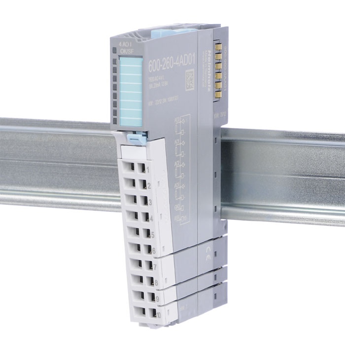
Analog output module - AO 4 x I, 0/4-20 mA, 12 Bit
Characteristics
•4 analog outputs, electrically isolated from the backplane bus
•4 process output words (8 bytes)
•Output ranges: 0-20 mA, 4-20 mA
•12-bit resolution
•Substitute value functionality
•Diagnostic messages
•A bi-color LED (blue/red) indicates the module’s operating status and any malfunctions
Parameters for the module
•Diagnostic alarm: On | Off
•Representation values: SIMATIC* S7 | SIMATIC* S5
Parameters for each channel
•Wire break detection: On | Off
•Output ranges: 0-20 mA | 4-20 mA
•Available substitute value options: De-energized outputs | Retain last value | Apply substitute value
•Substitute value: 16-bit analog value (±27648)
PART NUMBER | DESCRIPTION |
600-210-0AH01 | DI 8 x DC 24 V |
600-210-0AP21 | DI 16 x DC 24 V |
600-220-0AH01 | DO 8 x DC 24 V, 500 mA |
600-220-0AP21 | DO 16 x DC 24 V, 500 mA |
600-230-0AP21 | DIO 8 x Out/8 x In DC 24 V, 500 mA |
600-250-7BH21 | AI 8 x I, 0/4–20 mA, ±20 mA, Iso., 16 Bit |
600-253-4AD01 | AI 2/4 x R, RTD, 16 Bit, 2/3/4-Drah |
600-254-4AH22 | AI 8 x TC, Iso., 16 Bit |
600-260-4AD01 | AO 4 x I, 0/4–20 mA, 12 Bit |
File | Version | Size | Languages |
TP20, Manual modules | 5 | 11,638 MB |